A while back, I bought a few DDS modules through eBay. I used code from NR8O to program one of them and started pulling parts from the bin and pushing the output signal through the parts and into a load resistor.
Clik here to view.
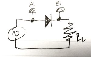
Experiment 1: Just a diode
Clik here to view.
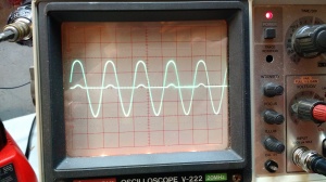
Result 1: the large waveform is the input signal (A), and the small bumps are the scope channel 2 (B). The diode rectifies the signal, which is why the bumps are only going up (and not down). The forward voltage drop on the diode is why the bumps are so small.
Clik here to view.
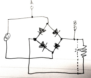
Experiment 2: a diode bridge
Clik here to view.
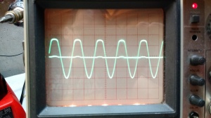
Result 2: This is similar to the circuit above, just more voltage drop because more diodes are involved.
Clik here to view.
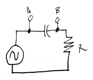
Experiment 3: Through a capacitor
Clik here to view.
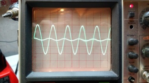
Result 3: the capacitor blocks DC, but allows AC through, with some voltage drop.
Clik here to view.
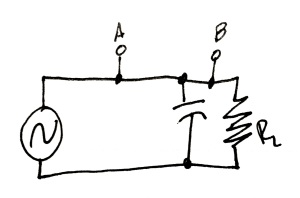
Experiment 4: Capacitor parallel with load.
Clik here to view.
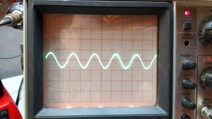
Result 4. No change because there is nothing between the test points.
Clik here to view.
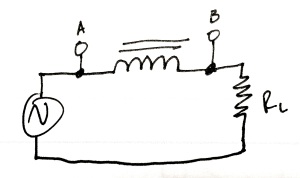
Experiment 5: through an inductor
Clik here to view.
Result 5: there was no change.
Clik here to view.
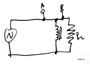
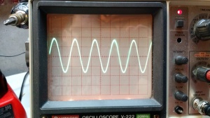
Experiment 6: inductive load
The video below shows what happened. I'm sure there's an explanation of the instability, but I don't know the explanation.
Stay tuned for experiments 2!
73 de KE8P